MH1000 vehicle flight tests activities
Introduction
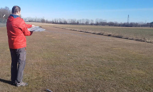
Flight test campaigns are a fundamental activity for all vehicles designed, prototyped and manufactured by MAVTech company. For the MH1000 fixed-wing model, the first days of flight tests have been carried out in January and February 2021, in order to test model performances, to optimise flight parameters and to verify the applicability of the vehicle to different types of mission. The flight tests campaign has been initially carried out in an airfield. Testing activities also include flight tests on cultivated fields, such as vineyards.
Activity description
Flight activities have been carried out following the completion of the design and mission definition phases. A series of preliminary activities have been also planned and completed, mainly divided into the following two steps:
Vehicle design and prototype construction
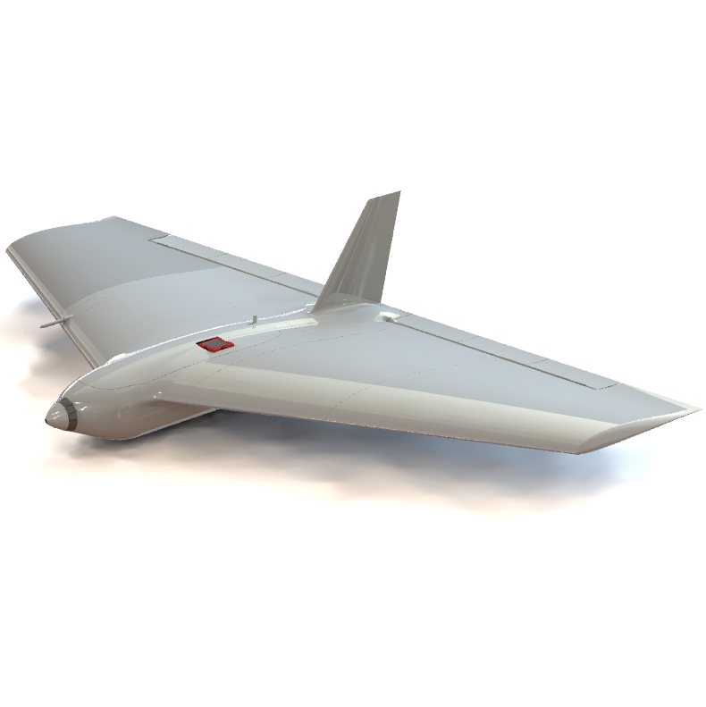
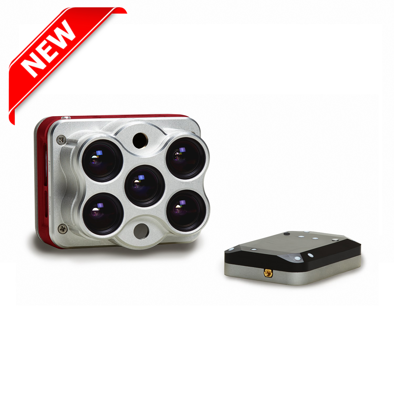
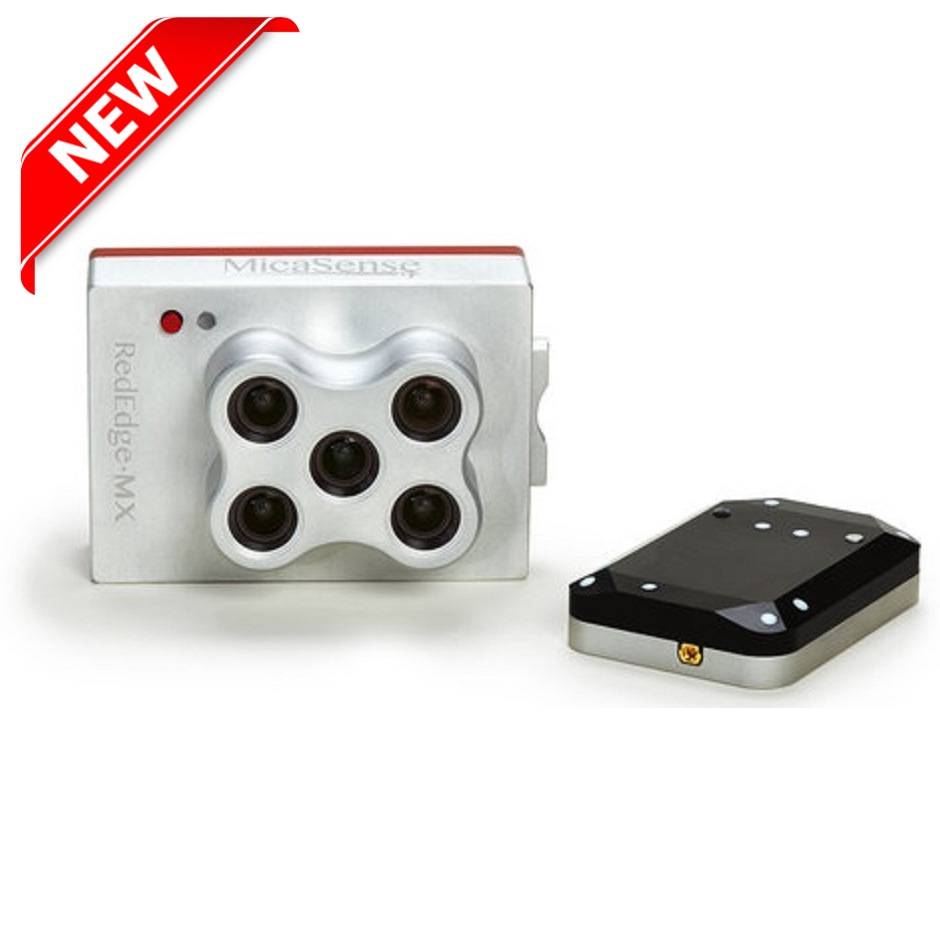
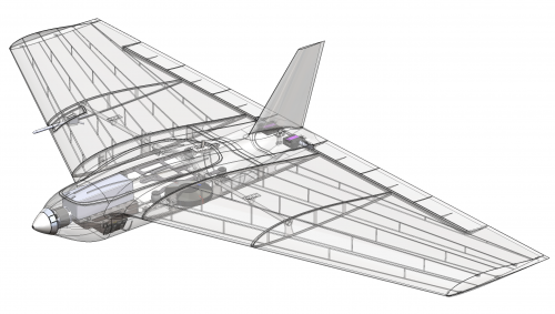
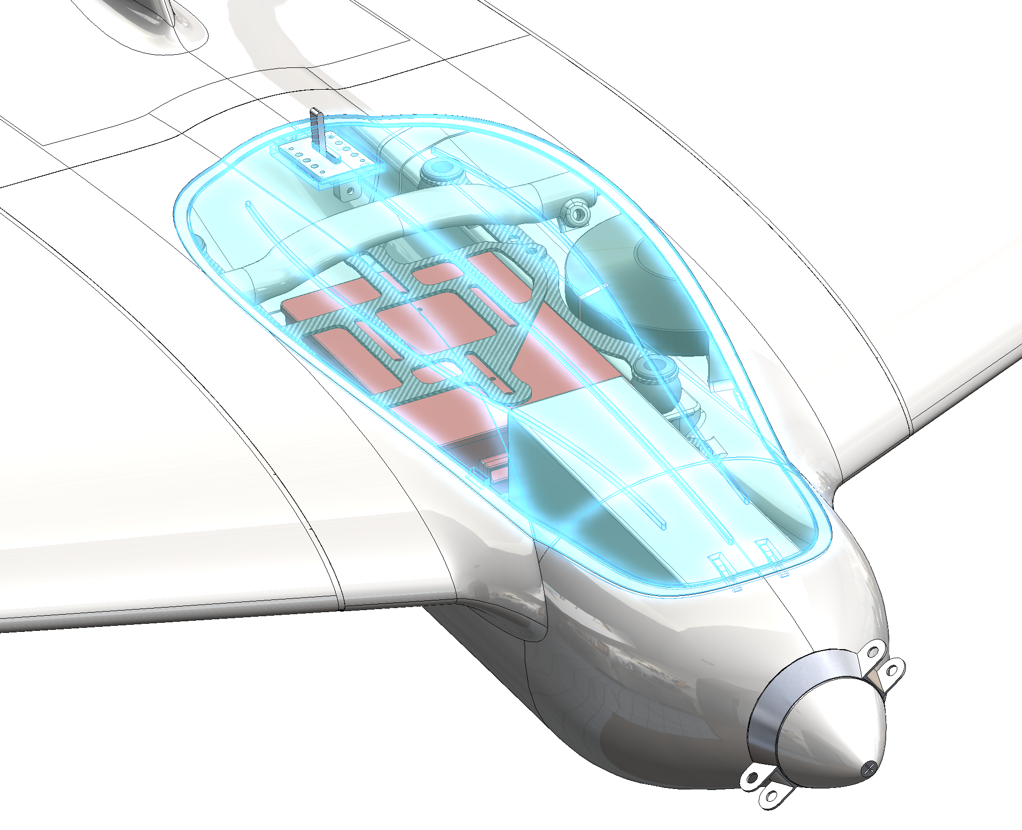
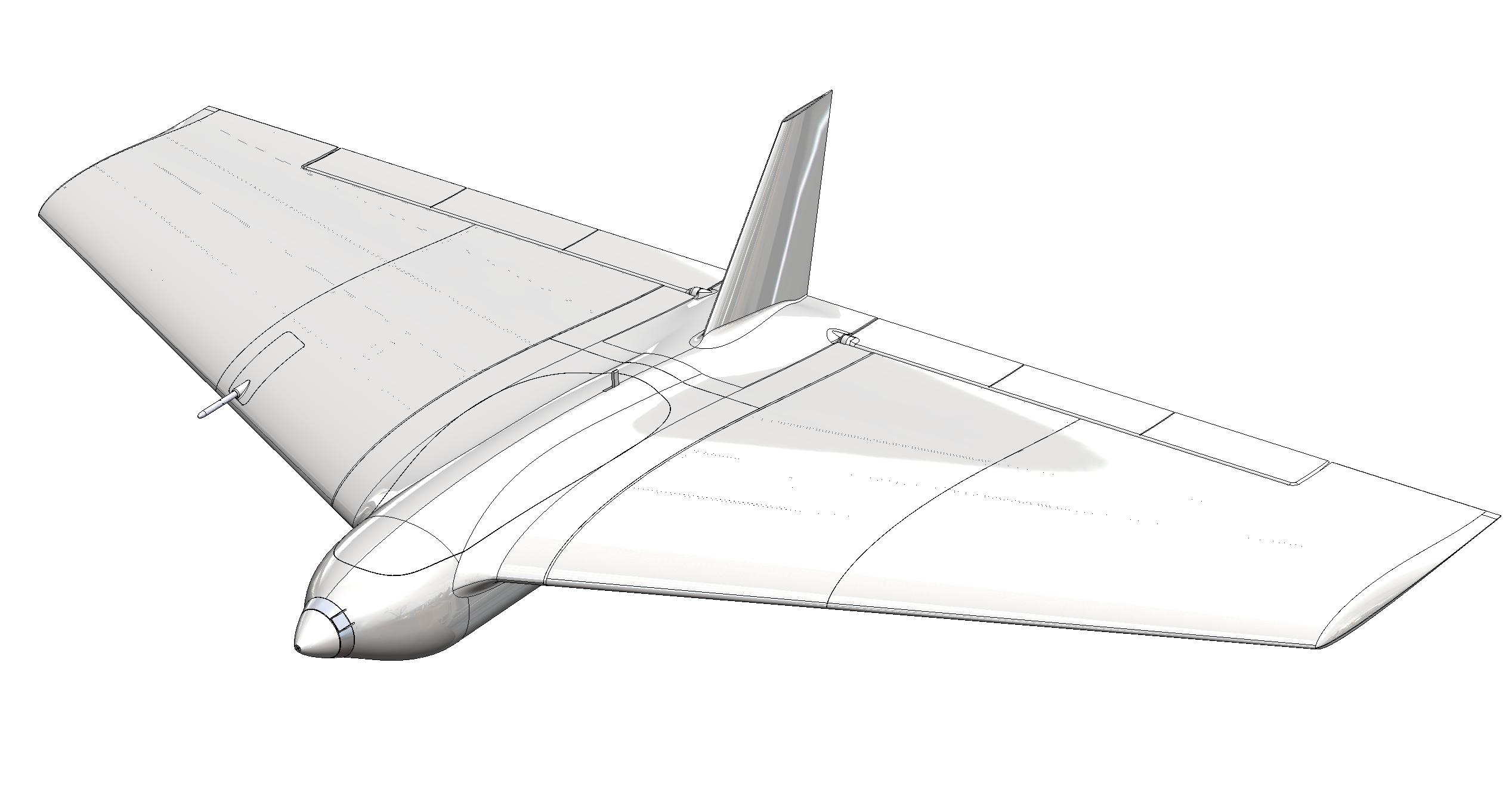
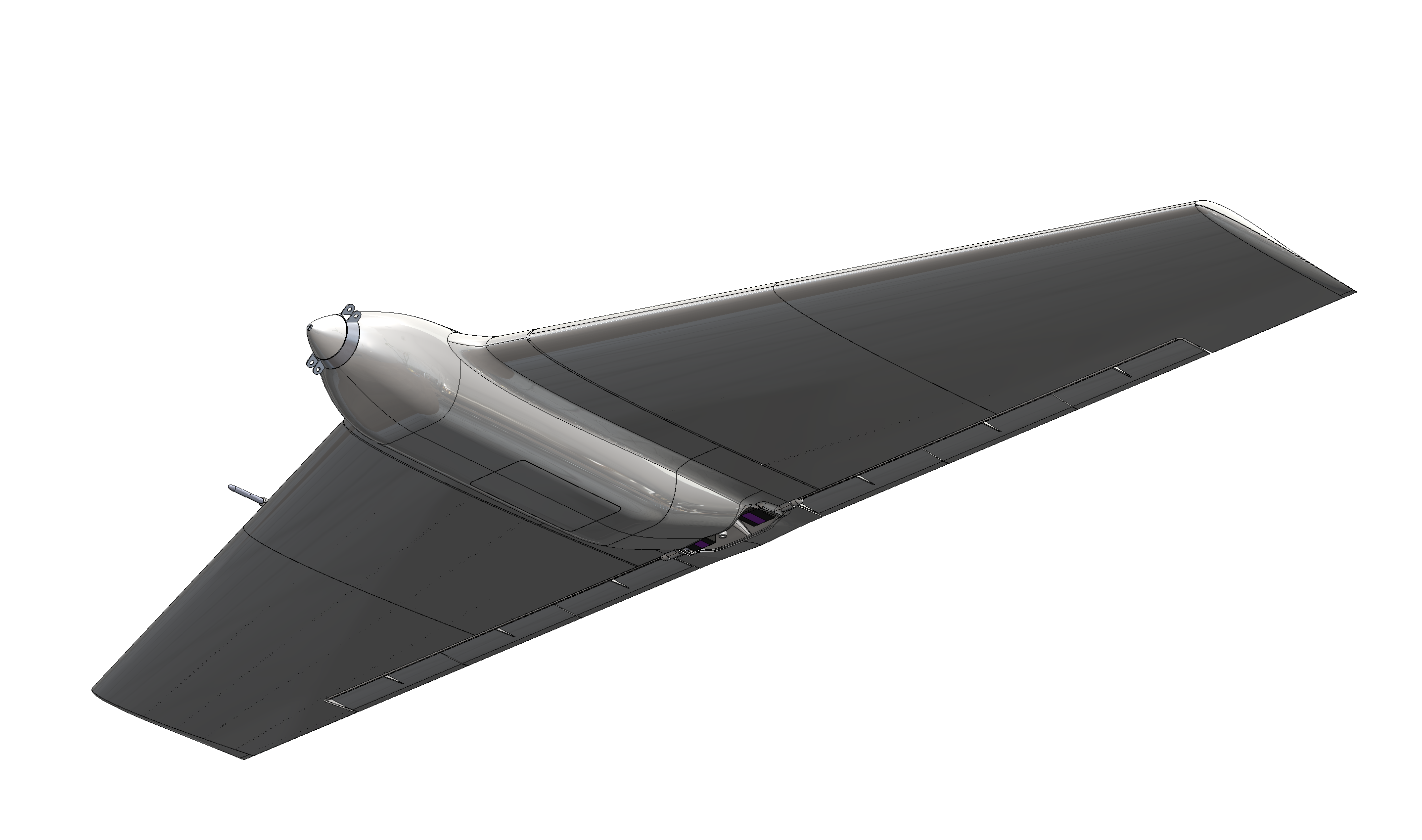
MH1000 has been entirely designed and prototyped by MAVTech team. It is a multifunctional fixed-wing Remotely Piloted Aircraft System (RPAS) designed primarily for carrying out reconnaissance, surveying and land surveillance missions. Thanks to its integrated wing-body configuration, its load capacity is suitable for the integration of specific sensors for surveying, such as the Micasense Rededge-M multispectral camera.

Flight tests and missions planning activities
Flight tests have been carried out following the study of flight parameters that can be varied and managed within the autopilot. These parameters are important to verify the manoeuvrability and the stability of the vehicle, for average cruise speed tests and for all take-off and landing performance checks. In addition, flight tests design phases also include the design of automatic missions, for example by simulating a grid survey with a multispectral sensor, which has been tested following the optimisation of the flight parameters. For the MH1000 model, the take-off phase has been experienced using a bungee launch system.
Results
Once the preliminary design and the prototyping phases have been completed, the flight activities begun!
Airfield experimental campaign
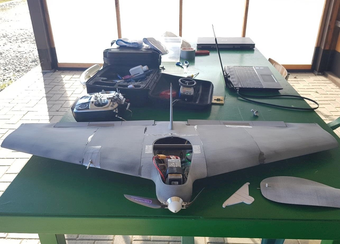
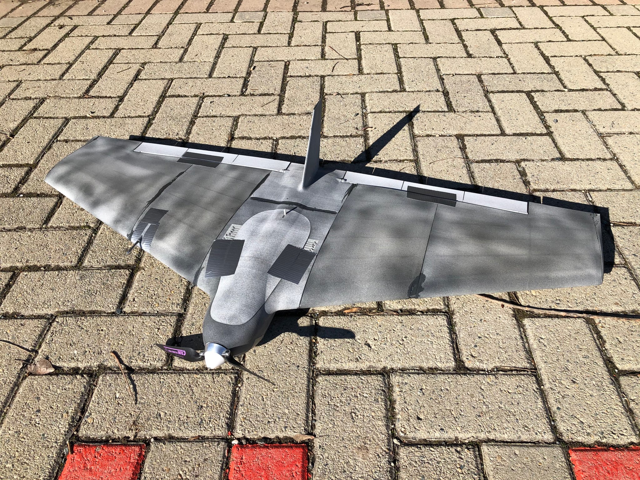
- Basic configuration: MH1000
- Weight: 1115 g
- Autopilot: Pixhawk 2 (FW Version: 4.0.7)
- Launch: with bungee system, STABILIZE flight mode


Flight logs analysis
The flights have been a success! They allowed us to optimise the flight parameters and improve the performance of the model, optimising it for the applications of interest.
After each day of flight tests, an activity is carried out that is essential for optimising the vehicle performances: the flights logs analysis and the evaluation of the quantities of interest. As a result of these analyses, it is possible to observe and study the occurrence of phenomena such as vehicle stall, the accuracy of automatic missions, performance in maintaining altitude and so on. It is also possible to obtain data on flight autonomy, vehicle stability and the interaction between the pilot's controls and the automatic management of flight speed and throttle by the autopilot in specific flight modes.
Autotune during flight: PID optimization
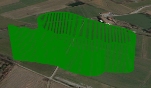
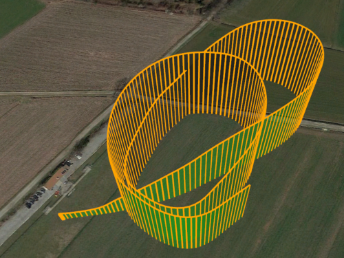
The figure shows the flight path made during the AUTOTUNE phase. In particular, it is visible the pitching trajectory made by the pilot, necessary for the automatic optimisation of the flight parameters.
STABILIZE flight mode analysis: test for altitude maintenance optimisation
During the second flight test, the STABILIZE and MANUAL flight modes have been tested, mainly by flying oval and semicircular trajectories. Flights in circles, performance in turns, climbing rates, gliding and altitude maintenance have been tested. It is observed that in the glide phases the vehicle had a quite loss of altitude. Also, during the turns it is evident the need to optimise the flight parameters for altitude maintenance. However, the altitude is recovered very quickly thanks to the thrust of the engine. The vehicle is potentially able to make a vertical climb.
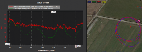
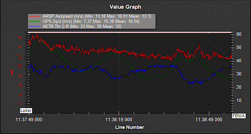
LOITER flight mode analysis: use of the Pitot tube
It can be observed that the ground speed (GPS_Spd) varies according to a periodic oscillation as a function of the flight path. This depends on the direction of the wind, which, during the completion of the same circular trajectory repeatedly, will be in some points in favour and in others against the direction of the vehicle's motion. The variation of the vehicle's momentum during the advancement of the trajectory and the areas in which it is upwind are thus observed.
Comparing speeds to the required throttle variation (AETR.Thr) further confirms this phenomenon. In fact, when the vehicle is in the upwind direction, there is a decrease in the relative speed and a consequent increase in throttle required to bring the speed back to the set cruise value. This allows the vehicle to compensate for the speed variation, maintaining a value measured by the Pitot tube that is approximately constant.
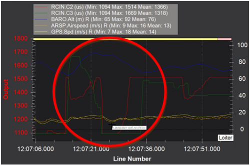
Stall testing
During the last flight tests the stall phenomenon is tested. In the graph it can be seen that, following an increase in the pitch command (RCIN.C2) and a decrease in the throttle command (RCIN.C3), an increase in altitude (BARO.Alt) and a decrease in relative flight speed and ground speed are observed, until a stall is reached. In this case, the stall occurs at a speed of approximately 9 m/s. It must be considered that this test has been carried out in FBWA mode, where the minimum speed maintenance parameter is active, in this case set to 10 m/s (parameter ARSPD_FBW_MIN). Also for this reason, a slight stall occurs. In fact, the vehicle immediately regains speed and a stable flight attitude. For future tests will be interesting to test the stall in STABILIZE mode, where the model is not limited by maintaining a minimum flight speed.
Automatic mission: flight performance test
Finally, the performance of the vehicle during the completion of an automatic mission is tested. First of all, the WP_RADIUS parameter is set to 10 m. This is the distance radius within which each mission waypoint is reached. Then, an automatic grid overflight mission is designed, whereby, once the vehicle is set to AUTO mode, the completion of the automatic mission will begin. In the figure it can be observed the variation in speed of the vehicle during the mission, visible on the map. The mission has been designed taking into account the specifications of the sensor that will constitute the payload on board the model. Consequently, the frequency of the shots and the flight altitude chosen in order to detect the entire monitored surface affected the the flight path planning phase.
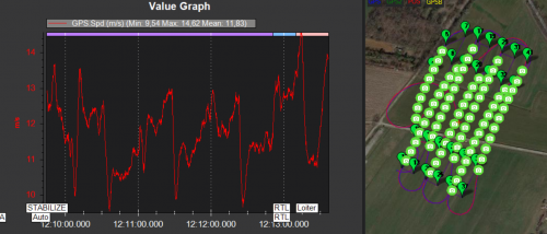
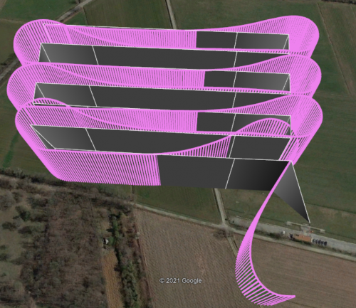
The mission is fully accomplished and at the end of the last flight trajectory segment the vehicle returns to HOME point, entering LOITER mode once the geographical launch position (engine armed) is reached. Flight performances are good. However, analysing the logs trajectory effectively flight by the vehicle, it is observed that the manoeuvring precision is not optimized to guarantee a trajectory completely overlapping the mission grid designed on before launch. This is due to the consideration of limited manoeuvring spaces. For example, by inserting the additional waypoints located outside the polygon to be flown over, which determine the lead-in and lead-out distances, at insufficient distances, the vehicle will not be able to perform appropriate manoeuvres.
This result can be observed in the following figure, which shows the grid designed during the automatic mission definition phase (grey) and the trajectory actually completed by the model (pink). It can be seen that only about half of each flight segment is carried out correctly in levelled flight. It is therefore necessary to optimise the flight parameters in AUTO mode and, at the same time, to thoroughly analyse the design parameters of the mission planning phase.